Woodworker's Journal 2004 Summer, страница 59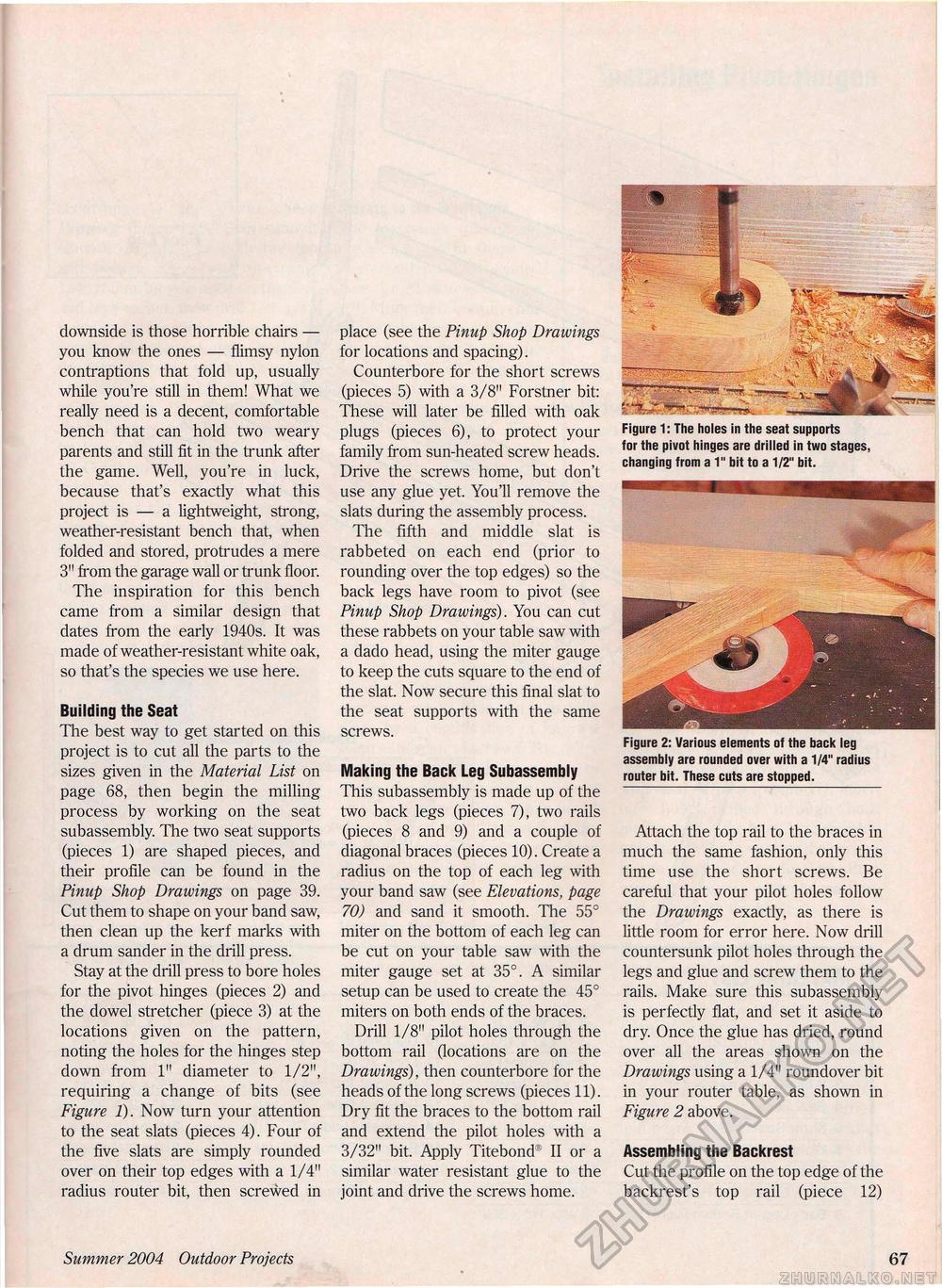
downside is those horrible chairs — you know the ones — flimsy nylon contraptions that fold up, usually while you're still in them! What we really need is a decent, comfortable bench that can hold two weary parents and still fit in the trunk after the game. Well, you're in luck, because that's exactly what this project is — a lightweight, strong, weather-resistant bench that, when folded and stored, protrudes a mere 3" from the garage wall or trunk floor. The inspiration for this bench came from a similar design that dates from the early 1940s. It was made of weather-resistant white oak, so that's the species we use here. place (see the Pinup Shop Drawings for locations and spacing). Counterbore for the short screws (pieces 5) with a 3/8" Forstner bit: These will later be filled with oak plugs (pieces 6), to protect your family from sun-heated screw heads. Drive the screws home, but don't use any glue yet. You'll remove the slats during the assembly process. The fifth and middle slat is rabbeted on each end (prior to rounding over the top edges) so the back legs have room to pivot (see Pinup Shop Drawings). You can cut these rabbets on your table saw with a dado head, using the miter gauge to keep the cuts square to the end of the slat. Now secure this final slat to the seat supports with the same screws. Making the Back Leg Subassembly This subassembly is made up of the two back legs (pieces 7), two rails (pieces 8 and 9) and a couple of diagonal braces (pieces 10). Create a radius on the top of each leg with your band saw (see Elevations, page 70) and sand it smooth. The 55° miter on the bottom of each leg can be cut on your table saw with the miter gauge set at 35°. A similar setup can be used to create the 45° miters on both ends of the braces. Drill 1/8" pilot holes through the bottom rail (locations are on the Drawings), then counterbore for the heads of the long screws (pieces 11). Dry fit the braces to the bottom rail and extend the pilot holes with a 3/32" bit. Apply Titebond® II or a similar water resistant glue to the joint and drive the screws home. Figure 1: The holes in the seat supports for the pivot hinges are drilled in two stages, changing from a 1" bit to a 1/2" bit. Building the Seat The best way to get started on this project is to cut all the parts to the sizes given in the Material List on page 68, then begin the milling process by working on the seat subassembly. The two seat supports (pieces 1) are shaped pieces, and their profile can be found in the Pinup Shop Drawings on page 39. Cut them to shape on your band saw, then clean up the kerf marks with a drum sander in the drill press. Stay at the drill press to bore holes for the pivot hinges (pieces 2) and the dowel stretcher (piece 3) at the locations given on the pattern, noting the holes for the hinges step down from 1" diameter to 1/2", requiring a change of bits (see Figure 1). Now turn your attention to the seat slats (pieces 4). Four of the five slats are simply rounded over on their top edges with a 1/4" radius router bit, then screwed in Attach the top rail to the braces in much the same fashion, only this time use the short screws. Be careful that your pilot holes follow the Drawings exactly, as there is little room for error here. Now drill countersunk pilot holes through the legs and glue and screw them to the rails. Make sure this subassembly is perfectly flat, and set it aside to dry. Once the glue has dried, round over all the areas shown on the Drawings using a 1/4" roundover bit in your router table, as shown in Figure 2 above. Assembling the Backrest Cut the profile on the top edge of the backrest's top rail (piece 12) Summer 2004 Outdoor Projects 67 |


